Iranian Classification Society Rules

< Previous | Contents | Next >
Section 4 Steel Tubes and Pipes
401. Steel tubes for boilers and heat exchangers
1. Application
(1) The
side ers,
requirements are mainly to apply to steel tubes intended for heat transfer at inside or out- of the tubes; for example, smoke tubes, water tubes, stay tubes, superheater tubes of boil- other tubes for high temperature heat exchangers, etc. (hereinafter referred to as "steel
tubes").
(2) Steel tubes other than those specified in (1) are to comply with the requirements in 101. 2.
2. Kinds
The steel tubes are classified as specified in Table 2.1.41.
Table 2.1.41 Kinds
Description | Grade | ||
Carbon steel tubes for | RSTH | 35 | RSTH 42 |
boilers and heat exchangers | RSTH | 52 | |
Alloy steel tubes for | RSTH | 12 | RSTH 22 |
boilers and heat exchangers | RSTH | 23 | RSTH 24 |
3. Heat treatment
The heat treatment of steel tubes is to comply with the requirements given in Table 2.1.42.
![]()
![]()
Table 2.1.42 Heat treatment See Guidance
Grade | Seamless steel tube | Electric-resistance welded steel tube | |||
Hot working | Cold working | As weld | Hot working | Cold working | |
RSTH 35 | As drawn | Low temperature an- nealed, Normalized or full annealed | Normalized | As drawn | Normalized(1) |
RSTH 42 | Low temperature an- nealed | ||||
RSTH 52 | Normalized | ||||
RSTH 12 | Low temperature annealed, Isothermal annealed, Full annealed, Normalized or Normalized and tempered(2) | ||||
RSTH 22 | Low temperature annealed , Isothermal annealed, Full annealed or Normalized and tempered(2) | ||||
RSTH 23 RSTH 24 | IsNotohremrmalaizledananneadletde,mFpuerlledanantea6l5e0d or and over | - | |||
NOTES (1) Steel tubes which are normalized prior to cold working may be finished by annealing (2) Low temperature annealing is not to be applied to electric resistance welded steel tube | |||||
![]()
4. Chemical composition
The chemical composition of steel tubes is to comply with the requirements given in
![]()
![]()
2.1.43. See Guidance
Table
![]()
Table 2.1.43 Chemical Composition
Grade | Chemical composition (%) | ||||||
C | Si | Mn | P | S | Cr | Mo | |
RSTH 35 | 0.18 max. | 0.10~0.35 | 0.30~0.60 | 0.035 max. | 0.035 max. | - | - |
RSTH 42 | 0.32 max. | 0.30~0.80 | |||||
RSTH 52 | 0.25 max. | 1.00~1.50 | |||||
RSTH 12 | 0.10~0.20 | 0.10~0.50 | 0.30~0.80 | 0.45~0.65 | |||
RSTH 22 | 0.15 max. | 0.50 max. | 0.30~0.60 | 0.80~1.25 | |||
RSTH 23 | 0.50~1.00 | 0.030 max. | 0.030 max. | 1.00~1.50 | |||
RSTH 24 | 0.50 max. | 1.90~2.60 | 0.87~1.13 | ||||
NOTE: In case where approved by the Society, R STH 35 and R STH 42 may be the killed steel of below 0.10 % Si. | |||||||
![]()
![]()
5. Mechanical properties See Guidance
The mechanical properties of steel tubes are to comply with the following requirements.
(1) Tensile test : The tensile test of steel tubes
2.1.44.
is to comply with the requirements given in Table
![]()
Table 2.1.44 Mechanical Properties
Grade | Yield strength ( N/mm 2) | Tensile strength ( N/mm 2) | Elongation ( %) ( L=5.65 A) |
RSTH 35 | 175 min. | 340 min. | 26 (22) min. |
RSTH 42 | 255 min. | 410 min. | 21 (17) min. |
RSTH 52 | 295 min. | 510 min. | |
RSTH 12 | 205 min. | 380 min. | |
RSTH 22 RSTH 23 RSTH 24 | 410 min. | ||
NOTES: 1. The values of elongation in parenthesis are applicable to the test specimens taken transversely. In this case, the sampling material is to be heated 600 to 650 after flattened and annealed in order to make it free from strain. 2. In case where test specimen of non-tubular section is taken from an electric-resistance welded steel tube, the test specimen is to be taken from the parts that do not include the welded line. | |||
![]()
![]()
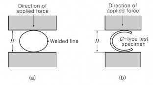
(2) Flattening test : A tubular section which is taken from the end of the steel tube is to stand be- ing flattened cold between parallel plates, without cracking or showing flaw, until the distance between the plates becomes less than the value of H calculated by the following formula. In this case, the length L of steel tube is to be not less than 50 mm, however, not more than 100 mm. For electric-resistance welded steel tubes, however, the welded line is to be placed at
right angle to the direction of the applied force as shown in Fig 2.1.9 (a) For tubes, of 15 % of outside diameter and over in thickness, C-type test specimen may be used, part of its circumference discarded as shown in Fig 2.1.9 (b)
however, having a
![]()
![]()
where:
![]() = Distance between flattening plates (mm).
= Distance between flattening plates (mm). ![]() = Thickness of steel tube (mm).
= Thickness of steel tube (mm).
![]() = Outside diameter of steel tube (mm).
= Outside diameter of steel tube (mm).
![]() = Constant given in Table 2.1.45 which varies according to the grade of steel tubes.
= Constant given in Table 2.1.45 which varies according to the grade of steel tubes.
![]()
Grade | Value of |
RSTH 35 | 0.09 |
RSTH 42, RSTH 12, RSTH 22, RSTH 23, RSTH 24 | 0.08 |
RSTH 52 | 0.07 |
Fig 2.1.9 Flattening test Table 2.1.45 Value of ![]()
(3) Flaring test : A section of steel tube which is taken from its end is to stand being flared cold with a tool having an included angle of 60 degrees, until the steel tube at the mouth of the flare is expanded without cracking or showing flaw to the diameter shown in Table 2.1.46. The rate of penetration of the mandrel shall not exceed 50 mm/min. In this case, the length of test specimen is to be 1.5 D , however, not less than 50 mm.
Table 2.1.46 Outside Diameter of Steel Tube End after Flaring
Grade | Outside diameter of steel tube end |
RSTH 35, RSTH 42, RSTH 52 | 1.2 times the outside diameter of steel tube |
RSTH 12, RSTH 22, RSTH 23, RSTH 24 | 1.14 times the outside diameter of steel tube |
(4) Reverse flattening test : A section of steel tube of 100 mm in length which is taken from the steel tube is to be slotted longitudinally on the opposite side of the welded line, opened and flattened without cracking or showing flaw on the inside of the welded line. There is also to be no misalignment, lack of penetration and overlap. But, this test is applied for electric-resist- ance welded steel tubes only.
(5) Hydraulic test :
(a) Steel tubes are to be hydraulically tested to a satisfactory result by 2 times and over the
(b)
maximum working pressure at the mill. The test pressure prescribed in (a) need
formula:
But the minimum test pressure is to be 7 M P a.
not exceed the pressure calculated by the following
![]()
![]()
where:
![]() = Thickness of steel tube (mm)
= Thickness of steel tube (mm)
![]() = Outside diameter of steel tube (mm)
= Outside diameter of steel tube (mm)
![]()
![]()
![]()
![]() = 60 of the prescribed minimum yield strength (N m m )
= 60 of the prescribed minimum yield strength (N m m )
(c) Where each steel tube is hydraulically tested as a regular procedure during the process of manufacturing at the mill, which makes a number of steel tubes continually, and the results are forwarded to the Surveyor, the test in the presence of the Surveyor may be dispensed with.
![]()
![]()
(d) A non-destructive inspection deemed appropriate by the Society may be substituted for the hydraulic test specified in (a). See Guidance
![]()
![]()
6. Selection of test specimen See Guidance
The test specimens are to be taken in accordance with the following requirements, from each grade and each size which has been heat treated at the same time in the same heating furnace for heat- treated tubes and from each grade and each size for non-heat-treated steel tubes respectively.
(1) Seamless steel tubes
One sampling steel tube is to be selected from each lot of 50 tubes or fraction thereof and each one specimen for tensile test, flattening test and flaring test is to be taken from each sam- pling steel tube.
(2) Electric-resistance welded steel tubes
For electric-resistance welded steel tubes, in addition to the requirements in (1), one sampling steel tube is to be selected from each lot of 100 tubes or fraction thereof, and one reverse flat-
tening test specimen is to be taken from each of the sampling steel tubes.
7. Tolerance for dimensions
The tolerances for the outside diameter and thickness are to comply with the requirements in Table
2.1.47. and Table 2.1.48. respectively.
![]()
![]()
Table 2.1.47 Tolerance for Outside Diameter of steel Tubes
Outside diameter of steel tube (mm) | Tolerance for Outside Diameter (mm) | |||
Seamless steel tube | Electric-resistance welded steel tube | |||
Hot finished | Cold working | Other than cold working | Cold working | |
<25 | + 0.4 - 0.8 | ± 0.10 | ± 0.15 | ± 0.10 |
25 <40 | ± 0.15 | ± 0.20 | ± 0.15 | |
40 <50 | ± 0.20 | ± 0.25 | ± 0.20 | |
50 <60 | ± 0.25 | ± 0.30 | ± 0.25 | |
60 <80 | ± 0.30 | ± 0.40 | ± 0.30 | |
80 <100 | ± 0.40 | + 0.40 - 0.60 | ± 0.40 | |
100 | + 0.4 - 1.2 | + 0.40 - 0.60 | + 0.40 - 0.80 | + 0.40 - 0.60 |
120 | + 0.40 - 0.80 | + 0.40 - 1.00 | + 0.40 - 0.80 | |
160 | + 0.4 - 1.6 | + 0.40 - 1.20 | + 0.40 - 1.20 | + 0.40 - 1.20 |
200 | + 0.4 - 1.8 | + 0.40 - 1.60 | + 0.40 - 1.60 | + 0.40 - 1.60 |
![]()
![]()
![]()
![]()
![]()
![]()
![]()
![]()
![]()
Table 2.1.48 Tolerance for thickness
Kind | Thickness t (mm) Outside diameter D (mm) | <2 | 2 <2.4 | 2.4 <3.8 | 3.8 <4.6 | 4.6 |
Hot finished seamless steel tube | < 100 | - | +40 % 0 % | +35 % 0 % | +33 % 0 % | +28 % 0 % |
100 | - | |||||
Cold drawn seamless steel tube and Electric-resistance welded steel tube of cold working | < 40 | +0.4mm 0 mm | +22 % 0 % | |||
40 | +22 %, 0 % | |||||
Electric-resistance welded steel tube of other than cold working | < 40 | +0.3mm 0 mm | +18 % 0 % | |||
40 | +18 %, 0 % | |||||
NOTE: For hot finished seamless steel tubes. the tolerance for deviation in wall thickness is to be 22.8 % and under of the thickness of the steel tube. But, for steel tubes of less than 5.6 mm in thickness, this note is not applied. | ||||||
![]()
![]()
8. Quality
(1) Each steel tubes are hydraulically or non-destructively tested as a regular procedure during the process of manufacturing at the mill and are free from leakages or harmful defects.
(2) The steel tubes are to be of uniform quality. For electric-resistance welded steel tubes, deposit
metal projected on outside of tubes is to be removed and finished smooth and that projected on inside of tubes is to be removed to have a height not more than 0.25 mm.
9. Retest procedures
Where the tensile test, flattening test, flaring test or reverse flattening test fails to meet the require- ments, additional tests may be conducted according to the requirements given in 109.
10. Marking
(1) The name or brand of the manufacturer, grade of tubes, size and symbol of the method of the manufacture relating to (2) below are to be legibly stamped or stenciled before shipment on each length steel tube in case of 30 mm and above in outside diameter and on each bundle or container of steel tubes in case of less than 30 mm in outside diameter. The Society"s brand indicating compliance with the requirements is to be stamped in the vicinity of the foregoing marks.
(2) The symbols indicating the method of manufacture are to be as specified in the following:
Hot finished seamless steel tube ············································································ Cold drawn seamless steel tube ············································································· Electric-resistance welded steel tube of other than hot and cold working ······ Electric-resistance welded steel tube of hot working ········································· Electric-resistance welded steel tube of cold working ·········································
-S-H
-S-C
-E -G
-E -H
-E -C
402. Steel pipes for pressure piping
1. Application
(1) These requirements are mainly to apply to steel pipes intended for use in piping which as "steel pipes").
(2) Steel pipes for general purpose specified in
seamless steel pipes and electric-resistance welded is prescribed in Pt 5, Ch 6 (hereinafter referred to
102. 2 (4) of Pt 5, Ch 6 are to comply with the
requirements of K S D 3507(SPP) or equivalent thereto. However, tests in the presence of the Surveyor are not required.
(3) The steel pipes having characteristics differing from those specified in 402. are to comply with
![]()
the requirements in 101. 2.
![]()
2. Kinds
The steel pipes are classified as specified in Table 2.1.49.
Table 2.1.49 Grades of Steel Pipes
Kind | Grade | Schedule applied |
Grade 1 Carbon steel pipe for pressure service | RST 138 RST 142 | Sch.10~Sch.80 |
Grade 2 Carbon steel pipe for high pressure service | RST 238 RST 242 RST 249 | Sch.40~Sch.160 |
Grade 3 Carbon steel pipe for high temperature service | RST 338 RST 342 RST 349 | Sch.10~Sch.160 |
Grade 4 Alloy steel pipe | RST 412 RST 422 RST 423 RST 424 |
3. Heat treatment
The heat treatment of steel pipes is to comply with the requirements given in Table 2.1.50.
![]()
Table 2.1.50 Heat treatment
Grade | Seamless steel pipe | Electric-resistance welded steel pipe | ||||
Hot finished | Cold drawn | As drawn | Hot finished | Cold finished | ||
Grade1 | RST 138 RST 142 | As drawn | Annealed | As drawn | As drawn | Annealed |
Grade2 | RST 238 | Low temperature annealed or | - | |||
RST 242 | ||||||
RST 249 | Normalized | |||||
Grade3 | RST 338 RST 342 | As drawn | Low temperature annealed or Normalized | Low temper- ature annealed or Normalized | As drawn | Low temperature annealed or Normalized |
RST 349 | - | |||||
Grade4 | RST 412 | Low temperature annealed Isothermal annealed, Full annealed, Normalized or Normalized and tempered | ||||
RST 422 | Low temperature annealed , Isothermal annealed, Full annealed or Normalized and tempered | |||||
RST 423 RST 424 | Isothermal annealed, Full annealed or Normalized and tempered at 650 and over | |||||
![]()
4. Chemical composition
The chemical composition of steel pipes is to comply with the requirements given in Table 2.1.51.
![]()
Table 2.1.51 Chemical Composition
Grade | Chemical composition ( ) | |||||||
C | Si | Mn | P | S | Cr | Mo | ||
Grade 1 | RST 138 | 0.25 max. | 0.35 max. | 0.30~0.90 | 0.040 max. | 0.040 max. | - | - |
RST 142 | 0.30 max. | 0.30~1.00 | ||||||
Grade 2 | RST 238 | 0.25 max. | 0.10~0.35 | 0.30~1.10 | 0.035 max. | 0.035 max. | ||
RST 242 | 0.30 max. | 0.30~1.40 | ||||||
RST 249 | 0.33 max. | 0.30~1.50 | ||||||
Grade 3 | RST 338 | 0.25 max. | 0.30~0.90 | |||||
RST 342 | 0.30 max. | 0.30~1.00 | ||||||
RST 349 | 0.33 max. | |||||||
Grade 4 | RST 412 | 0.10~0.20 | 0.10~0.50 | 0.30~0.80 | 0.45~0.65 | |||
RST 422 | 0.15 max. | 0.50 max. | 0.30~0.60 | 0.80~1.25 | ||||
RST 423 | 0.50~1.00 | 0.030 max. | 0.030 max. | 1.00~1.50 | ||||
RST 424 | 0.50 max. | 1.90~2.60 | 0.87~1.13 | |||||
5. Mechanical properties
The mechanical properties of steel pipes are to comply with the following requirements.
(1) Tensile test : The tensile test of
2.1.52.
![]()
![]()
![]()
![]()
![]()
![]()
![]()
![]()
Table 2.1.52 Mechanical Properties
steel pipes are to comply with the requirements given in Table
Grade | Yield strength (N m m ) | Tensile strength (N mm ) | Elongation ( )( ) | |
Grade 1 Grade 2 Grade 3 | RST 138 RST 238 RST 338 | 215 min. | 370 min. | 24 (20) min. |
Grade 1 Grade 2 Grade 3 | RST 142 RST 242 RST 342 | 245 min. | 410 min. | 21 (17) min. |
Grade 2 Grade 3 | RST 249 RST 349 | 275 min. | 480 min. | 19 (15) min. |
Grade 4 | RST 412 | 205 min. | 380 min. | 21(17) min. |
Grade 4 | RST 422 RST 423 RST 424 | 410 min. | ||
NOTES: 1. The requirements for elongation given in parentheses in the Table are applied for the case where test specimens are taken transversely. In this case, the test sample is to be stress relieved at the temperature of 600 to 650 after flattened. 2. In case where test specimen of non-tubular section is taken from electric-resistance welded steel pipes, the test specimen is to be taken from the part that does not include a welded line. | ||||
![]()
(2) Flattening test
(a) Pipes other than Grade 1 of electric-resistance welded steel pipe: A tubular section of steel
pipe which is taken from the end of the steel pipe, is to stand being flattened between par- allel plates, without cracking or showing flaw, until the distance between the plates becomes
less than the value of H calculated by the following formula. In this case, the length of
test specimen is to comply with the requirements in 401.5 (2). For steel pipes, however, of 15 % of outside diameter and above in thickness, C-type test specimen may be used, having a part of its circumference discarded as shown in Fig 2.1.9 (b)
![]()
Table
where:
![]() = Distance between flattening plates (mm).
= Distance between flattening plates (mm). ![]() = Thickness of steel pipe (mm).
= Thickness of steel pipe (mm).
![]() = Outside diameter of steel pipe (mm).
= Outside diameter of steel pipe (mm).
![]() = Constant given in Table 2.1.53 which varies according tubes.
= Constant given in Table 2.1.53 which varies according tubes.
![]()
2.1.53 value of
to the grade of steel
Grade | RST 142, RST 242, RST 249, RST 342 RST 349 | RST 138, RST 238, RST 338, RST 412 RST 422, RST 423, RST 424 |
| 0.07 | 0.08 |
(b) Electric-resistance welded steel pipes Grade 1 :
![]()
for welded line, for elsewhere.
In case of electric-resistance welded steel pipes, the welded line is to gle to the direction of the applied force, as in Fig 2.1.10.
be placed at right an-
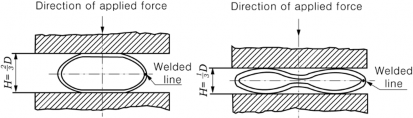
Fig 2.1.10 Flattening test of electric-resistance welded steel pipes Grade 1
(3) Bend test : For steel pipes of 50 mm and
under in outside diameter, the specimen for flattening
test may be substituted for that for bend which is taken from the end of the steel
test. pipe
In this case, a test specimen of tubular section and has sufficient length is to stand being bent
cold, up to the specified value in Table 2.1.54, without cracking
But, for Grade 4, this test need not be carried out.
or showing flaw on the wall.
![]()
Table 2.1.54 Bend Test
Grade | Angle of bending | Inside bend radius |
1, 2 and 3 | 90° | 6 times the outside diameter of steel pipe |
NOTE: Electric-resistance welded steel pipes are to be so bent as the welded line is placed widest. | ||
(4) Hydraulic test
(a) Grade 1 steel pipes are to be hydraulically tested with the pressure specified in Table 2.1.55.
(b)
In case where the test pressure higher than prescribed in (a) is specified by the purchaser for Grade 2 through 4 steel pipes, the test is to be carried out with the specified pressure. In this case, test pressure need not exceed the pressure calculated by the following formula:
![]()
![]()
Mpa
where :
![]()
= Hydraulic test pressure (MPa).
![]()
![]()
= Outside diameter of steel pipe (mm). ![]() = Thickness of steel pipe (mm).
= Thickness of steel pipe (mm).
![]()
![]() = 60 of the prescribed minimum yield strength (N m m ).
= 60 of the prescribed minimum yield strength (N m m ).
(c) When each steel pipe is hydraulically tested as a regular procedure during the process of manufacturing at the mill which makes a number of steel tubes continually, and the results are forwarded to the Surveyor, the test in the presence of the Surveyor may be dispensed with.
(d)
A non-destructive inspection deemed appropriate by the Society may be substituted for the hydraulic inspection specified in (a).
6. Selection of test specimen
(1) Grade 1 : Sampling steel pipes are to be selected as following requirements in connection with the nominal diameter of steel pipes specified in Table 2.1.55 and each one specimen for ten- sile test, flattening test or bend test is to be taken from each sampling steel pipe.
(a) For steel pipes less than 65A in nominal diameter : One sampling steel pipe is to be se- lected from each lot of 1000 pipes or fraction thereof.
(b)
(c)
(d)
For steel pipes which a nominal diameter is 65A or above and less than 150A : One sam-
pling steel pipe is to be selected from each lot of 500 pipes or fraction thereof.
For steel pipes which a nominal diameter is 150A or above and less than 350A : One sampling steel pipe is to be selected from each lot of 250 pipes or fraction thereof.
For steel pipes more than 350A in nominal diameter : One sampling steel pipe is to be se-
lected from each lot of 150 pipes or fraction thereof.
(2) Grade 2 : One sampling steel pipe is to be selected from each lot of 50 pipes or fraction thereof, and each one specimen for tensile test and flattening test or bend test is to be taken from each sampling steel pipe.
(3) Grade 3
Selection of test specimen is to comply with the requirements in (2).
(4) Grade 4 : One sampling steel pipe is to thereof, and each one specimen for tensile from each sampling steel pipe.
be selected from each lot of 50 pipes or fraction test and flattening test or bend test is to be taken
![]()
![]()
Table 2.1.55 Schedule and Hydraulic Test Pressure
Nominal diameter (A) | Outside diameter (mm) | Nominal thickness (mm) | |||||||||
Sch.10 (10S) | Sch.20 (20S) | Sch.30 | Sch.40 | Sch.60 | Sch.80 | Sch.100 | Sch.120 | Sch.140 | Sch.160 | ||
6 | 10.5 | (1.2) | (1.5) | - | 1.7 | 2.2 | 2.4 | - | - | - | - |
8 | 13.8 | (1.65) | (2.0) | - | 2.2 | 2.4 | 3.0 | - | - | - | - |
10 | 17.3 | (1.65) | (2.0) | - | 2.3 | 2.8 | 3.2 | - | - | - | - |
15 | 21.7 | (2.1) | (2.5) | - | 2.8 | 3.2 | 3.7 | - | - | - | 4.7 |
20 | 27.2 | (2.1) | (2.5) | - | 2.9 | 3.4 | 3.9 | - | - | - | 5.5 |
25 | 34.0 | (2.8) | (3.0) | - | 3.4 | 3.9 | 4.5 | - | - | - | 6.4 |
32 | 42.7 | (2.8) | (3.0) | - | 3.6 | 4.5 | 4.9 | - | - | - | 6.4 |
40 | 48.6 | (2.8) | (3.0) | - | 3.7 | 4.5 | 5.1 | - | - | - | 7.1 |
50 | 60.5 | (2.8) | 3.2(3.5) | - | 3.9 | 4.9 | 5.5 | - | - | - | 8.7 |
65 | 76.3 | (3.0) | 4.5(3.5) | - | 5.2 | 6.0 | 7.0 | - | - | - | 9.5 |
80 | 89.1 | (3.0) | 4.5(4.0) | - | 5.5 | 6.6 | 7.6 | - | - | - | 11.1 |
90 | 101.6 | (3.0) | 4.5(4.0) | - | 5.7 | 7.0 | 8.1 | - | - | - | 12.7 |
100 | 114.3 | (3.0) | 4.9(4.0) | - | 6.0 | 7.1 | 8.6 | - | 11.1 | - | 13.5 |
125 | 139.8 | (3.4) | 5.1(5.0) | - | 6.6 | 8.1 | 9.5 | - | 12.7 | - | 15.9 |
150 | 165.2 | (3.4) | 5.5(5.0) | - | 7.1 | 9.3 | 11.0 | - | 14.3 | - | 18.2 |
200 | 216.3 | (4.0) | 6.4(6.5) | 7.0 | 8.2 | 10.3 | 12.7 | 15.1 | 18.2 | 20.6 | 23.0 |
250 | 267.5 | (4.0) | 6.4(6.5) | 7.8 | 9.3 | 12.7 | 15.1 | 18.1 | 21.4 | 25.4 | 28.6 |
300 | 318.5 | (4.5) | 6.4(6.5) | 8.4 | 10.3 | 14.3 | 17.4 | 21.4 | 25.4 | 28.6 | 33.3 |
350 | 355.6 | 6.4 | 7.9 | 9.5 | 11.1 | 15.1 | 19.0 | 23.8 | 27.8 | 31.8 | 35.7 |
400 | 406.4 | 6.4 | 7.9 | 9.5 | 12.7 | 16.7 | 21.4 | 26.2 | 30.9 | 36.5 | 40.5 |
450 | 457.2 | 6.4 | 7.9 | 11.1 | 14.3 | 19.0 | 23.8 | 29.4 | 34.9 | 39.7 | 45.2 |
500 | 508.0 | 6.4 | 9.5 | 12.7 | 15.1 | 20.6 | 26.2 | 32.5 | 38.1 | 44.4 | 50.0 |
550 | 558.8 | 6.4 | 9.5 | 12.7 | 15.9 | 22.2 | 28.6 | 34.9 | 41.3 | 47.6 | 54.0 |
600 | 609.4 | 6.4 | 9.5 | 14.3 | 17.5 | 24.6 | 31.0 | 38.9 | 46.0 | 52.4 | 59.5 |
650 | 660.4 | 7.9 | 12.7 | - | 18.9 | 26.4 | 34.0 | 41.6 | 49.1 | 56.6 | 64.2 |
Hydraulic test pressure (M P a) | Grade 1 | 2.0 | 3.5 | 5.0 | 6.0 | 9.0 | 12.0 | - | - | - | - |
Grade 2 | - | - | - | 6.0 | 9.0 | 12.0 | 15.0 | 18.0 | 20.0 | 20.0 | |
Grade 3 and Grade 4 | 2.0 | 3.5 | 5.0 | 6.0 | 9.0 | 12.0 | 15.0 | 18.0 | 20.0 | 20.0 | |
NOTE: The values of nominal thickness in parentheses are applicable to stainless steel pipes. | |||||||||||
![]()
7. Tolerance for dimensions
Tolerances for the outside diameter and the
2.1.56.
thickness are to comply with the requirements in Table
![]()
Table 2.1.56 Tolerance for Dimensions
Kind | Outside diameter of steel pipe D (mm) | Tolerance for outside diameter | Tolerance for wall thickness | |||
Grade 1 | Grade 2, 3 and 4 | |||||
Hot finished seam- less steel pipe | D < 50 | ± 0.5 mm | Thickness of steel pipe: Less than 4 mm | + 0.6 mm - 0.5 mm | Thickness of steel pipe: Less than 4 m m | ± 0.5 mm |
D 50 | ± 1 % | Thickness of steel pipe: 4 mm and over | + 15 % - 12.5 % | Thickness of steel pipe: 4 m m and over | ± 12.5 % | |
Cold drawn seam- less steel pipe and electric-resistance welded steel pipe | D < 40 | ± 0.3 mm | Thickness of steel pipe: Less than 3 mm | ± 0.3 mm | Thickness of steel pipe: Less than 2 m m | ± 0.2 mm |
D 40 | ± 0.80 mm | Thickness of steel pipe: 3 mm and over | ± 10 % | Thickness of steel pipe: 2 mm and over | ± 10 % | |
NOTE: For hot finished seamless steel pipes Grades 2, 3 and 4, the tolerance for deviation in wall thick- ness is to be 20 % and under of the thickness of the pipes. But, for steel pipes less than 5.6 m m in thickness, this note is not applied. | ||||||
![]()
8. Quality
(1) Each steel pipes are hydraulically or harmful defects.
non-destructively tested and are free from leakages or
(2) The steel pipes are to be of uniform quality and free from harmful defects.
9. Retest procedures
Where the tensile test, flattening test or bend test fails to meet the requirements, additional tests may be conducted according to the requirements given in 109.
10. Marking
(1) The name or brand of the manufacturer, grade of steel tubes, size and symbol of the method of the manufacture relating to (2) below are to be legibly stamped or stenciled before shipment on each length steel tube in case of 60 mm and above in outside diameter and on each bundle or container of steel tubes in case of less than 60 mm in outside diameter. The Society's brand indicating compliance with the requirements is to be in the vicinity of the foregoing marks.
(2) The symbols indicating the method of manufacture are to comply with the requirement in 401.
10 (2).
403. Stainless steel pipes
1. Application
(1) The requirements are to apply to the stainless steel pipes for low temperature service or corro- sion-resistance service (hereinafter referred to as "stainless steel pipes").
(2) Stainless steel pipes having characteristics differing from those specified in 403. are to comply
![]()
with the requirements in 101. 2.
![]()
2. Kinds
The stainless steel pipes are classified as specified in Table 2.1.57.
![]()
Table 2.1.57 Grades and Chemical Composition
Grade | solid solution treatment(℃) | Chemical Composition ( ) | |||||||||
C | Si | M n | P | S | N i | C r | M o | O thers | |||
RSTS 304TP | 1010 and over, quenching | 0.080 max. | 1.00 max. | 2.00 max. | 0.040 max. | 0.030 max. | 8.00~11.00 | 18.00~20.00 | - | - | |
RSTS 304LTP | 1010 and over, quenching | 0.030 max. | 9.00~13.00 | ||||||||
RSTS 309STP | 1030 and over, quenching | 0.080 max. | 12.00~15.00 | 22.00~24.00 | |||||||
RSTS 310STP | 1030 and over, quenching | 1.50 max. | 19.00~22.00 | 24.00~26.00 | |||||||
RSTS 316TP | 1010 and over, quenching | 1.00 max. | 10.00~14.00 | 16.00~18.00 | 2.00~3.00 | ||||||
RSTS 316LTP | 1010 and over, quenching | 0.030 max. | 12.00~16.00 | ||||||||
RSTS 317TP | 1010 and over, quenching | 0.080 max. | 11.00~15.00 | 18.00~20.00 | 3.00~4.00 | ||||||
RSTS 317LTP | 1010 and over, quenching | 0.030 max. | |||||||||
RSTS 321TP | 920 and over, quenching | 0.080 max. | 9.00~13.00 | 17.00~19.00 | - | Ti 5×C | |||||
RSTS 347TP | 980 and over, quenching | Nb 10×C | |||||||||
![]()
![]()
3. Heat treatment
![]()
The stainless steel pipes are generally to receive a solid solution treatment. For RSTS 321TP and RbeSToSf 835407~T9P3,0 sta.bilizing treatment may be required. In this case, heat treatment temperature is to
4. Chemical composition
The chemical composition of stainless steel pipes is to comply with the requirements given in
Table 2.1.57.
5. Mechanical properties
(1) The mechanical properties of stainless steel pipes are to comply with the following requirements.
(a) Tensile test
The tensile test of stainless steel pipes is to comply with the requirements given in
2.1.58.
(b) Flattening test
Flattening tests are to be carried out in accordance with the requirements in 402.
However, where the requirements are applied, the value of e is to be taken as 0.09.
![]()
Table 5 (2).
![]()
![]()
![]()
![]()
![]()
![]()
Table 2.1.58 Tensile Test
Grade | Yield strength (N mm ) | Tensile strength (N mm ) | Elongation ( )( ) | |
L | T | |||
RSTS 304TP | 205 min. | 520 min. | 26 min. | 22 min. |
RSTS 304LTP | 175 min. | 480 min. | ||
RSTS 309STP | 205 min. | 520 min. | ||
RSTS 310STP | ||||
RSTS 316TP | ||||
RSTS 316LTP | 175 min. | 480 min. | ||
RSTS 317TP | 205 min. | 520 min. | ||
RSTS 317LTP | 175 min. | 480 min. | ||
RSTS 321TP | 205 min. | 520 min. | ||
RSTS 347TP | ||||
NOTES: 1. L (or T) denotes that the longitudinal axis of the test specimen is arranged parallel (or normal) to the final direction of rolling. 2. Where the nominal diameter of stainless steel pipes is 200 mm and over, tensile test specimens may be taken transversely. 3. Where test specimens of non-tubular section are taken from welded pipes, the test specimens are to be taken from the part that does not include the welded line. | ||||
(c) Hydraulic test
(i) Stainless steel
2.1.59.
pipes are to be hydraulically tested with the pressure specified in Table
Table 2.1.59 Hydraulic Test Pressure
Schedule No. | Sch.10S | Sch.20S | Sch.40 | Sch.80 | Sch.120 | Sch.160 |
Test pressure (M Pa) | 2.0 | 3.5 | 6.0 | 12.0 | 18.0 | 20.0 |
(ii) In case where the test pressure higher than prescribed in (a) is specified by the pur- chaser, the test is to be carried out with the specified pressure. In this case, the test pressure need not exceed the pressure calculated by the following formula:
![]()
![]()
Mpa
where:
![]()
= Hydraulic test pressure (MPa).
= Thickness of stainless steel pipe (mm).
= Outside diameter of stainless steel pipe (mm).
![]()
![]()
![]() = 60 % of the prescribed minimum yield strength (N m m ).
= 60 % of the prescribed minimum yield strength (N m m ).
(iii) When each pipe is hydraulically tested as a regular during the process of manufacturing at the mill which makes a number of tubes continually, and the results are forwarded to the Surveyor, the test in the presence of the Surveyor may be dispensed with.
![]()
(iv) A non-destructive inspection deemed appropriate by the Society may be substituted for the hydraulic test specified in (i).
![]()
(2) The Society may require the impact test or corrosion resistance test according to purposes of stainless steel pipes.
6. Selection of test specimens
One sampling pipe is to be selected from each lot of 50 pipes or fraction thereof which are of the same charge, size and kind and are simultaneously heat treated, and each one specimen for tensile test and flattening test is to be taken from each sample pipe.
7. Tolerance for dimensions
Tolerances for the outside diameter and the
2.1.60.
thickness are to comply with the requirements in Table
Table 2.1.60 Tolerance for Dimensions
Kind | Outside diameter of stainless steel pipe | Tolerance for wall thickness | ||
Hot-finished seamless stainless steel pipe | Less than 50 | ± 0.5 mm | Thickness of pipe: Less than 4 m m | ± 0.5 mm |
50 and over | ± 1 % | Thickness of pipe: 4 mm and over | ± 12.5 | |
Cold drawn seamless stainless pipe, automatic arc welded stainless steel pipe and electric-resistance welded stainless steel pipe | Less than 30 | ± 0.3 mm | Thickness of pipe: Less than 2 m m | ± 0.2 mm |
30m m and over | ± 1 | Thickness of pipe: 2 m m and over | ± 10 | |
NOTE: For hot finished seamless stainless steel pipes, the tolerance for deviation in wall thickness is to be 20 | ||||
8. Quality
(1) Each steel pipes are hydraulically or ful defects.
non-destructively tested and are free from leakages or harm-
(2) The stainless steel pipes are to be of uniform quality and free from harmful defects.
9. Retest procedures
Where the tensile test or flattening test fails to meet the requirements, additional tests may be con- ducted according to the requirements given in 109.
10. Marking
Stainless steel pipes which have satisfactorily complied with the required tests are to be marked with identification mark in accordance with the requirements in 402. 10. However, the symbols in- dicating the manufacturing method of automatic arc welded steel pipes are to be as specified in the following:
Automatic arc welded steel pipe : -A
Automatic arc welded and cold finished steel pipe : -A-C
Automatic arc welded and machined steel pipe : -A -B
404. Steel pipes for low temperature service
1. Application
![]()
(1) These requirements are to apply to the seamless steel pipes and electric resistance welded steel pipes not exceeding 25 mm in thickness, intended to be used at the design temperature lower than 0 in liquefied gas carriers (hereinafter referred to as "steel pipes").
![]()
![]()
![]()
(2) Any requirement regarding the steel pipes over 25 mm in thickness is left to the discretion of the Society. See Guidance
(3) Steel pipes having characteristics differing from those specified requirements in 101. 2.
2. Kinds
The steel pipes are classified as given in Table 2.1.61.
3. Deoxidation practice and chemical composition
The deoxidation practice and chemical composition of each grade ments given in Table 2.1.61.
in 404. are to comply with the
are to comply with the require-
![]()
Table 2.1.61 Grades and Chemical Composition ( )
Grade | Deoxidation | C | Si | M n | P | S | N i |
RLPA | Fully killed fine grain | 0.23 max. | 0.35 max. | 1.60 max. | 0.035 max. | 0.035 max. | - |
RLPB | 0.18 max. | 0.35 max. | 1.60 max. | 0.035 max. | 0.035 max. | - | |
RLPC | 0.18 max. | 0.35 max. | 1.60 max. | 0.035 max. | 0.035 max. | - | |
RLP 2 | 0.19 max. | 0.10~0.35 | 0.90 max. | 0.035 max. | 0.035 max. | 2.00~2.60 | |
RLP 3 | 0.16 max. | 0.10~0.35 | 0.90 max. | 0.030 max. | 0.030 max. | 3.20~3.80 | |
RLP 9 | 0.10 max. | 0.10~0.35 | 0.90 max. | 0.030 max. | 0.030 max. | 8.40~9.50 |
4. Heat treatment
The heat treatment of steel pipes is to comply with the requirements given in Table 2.1.62.
5. Mechanical properties
(1) The mechanical properties of steel pipes are to comply with the following (a) to (d).
(a) Tensile test
The tensile test of steel pipes is to comply with the requirements given in Table 2.1.62.
(b)
(c)
Impact test
The impact test of steel pipes is to comply with the requirements given in Table 2.1.62.
Flattening test
Flattening test is to be carried out in accordance with the requirements given in 402. 5 (2). Where this requirement is applied, the value of e is to be taken as 0.08. For steel pipes of 50 mm and under in outside diameter, the specimen for flattening test may be substituted for that for bend test. In this case, a test specimen of tubular section which is taken from the end of the steel pipe and has sufficient length is to stand being bent cold, up to the
specified value in Electric resistance
Table 2.1.62, without flaw and cracking on the outside of bent portion. welded steel pipes are to be bent at the place where the welded line is
(d)
on the outside of bent portion.
Hydraulic test
All steel pipes are to be subjected to hydraulic test in accordance with the requirements given in 402. 5 (4).
(2) Where deemed necessary by the Society, other tests may be required in addition to the tests specified in (1)
6. Selection of test specimens
(1) One sampling pipe is to be selected from each lot of 50 pipes or fraction thereof which are of
![]()
the same charge, size and kind and are simultaneously heat treated. tensile test and flattening test is to be taken from each sample pipe.
Each one specimen for
![]()
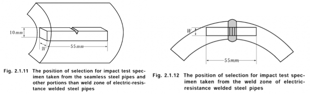
(2) One set of three specimens for impact test is to be taken from each sample pipe in accordance
with Fig 2.1.11. Moreover, for electric resistance welded specimens is to be taken from the welded zone in accordance
steel pipes, another set of three with Fig 2.1.12.
![]()
![]()
![]()
![]()
![]()
![]()
Table 2.1.62 Heat Treatment and Mechanical Properties
Grade | Heat treatment | Tensile test (1)(2)(3) | Bend test | Impact test | |||||
Yield strength (N m m ) | Tensile strength (N mm ) | Elongation (%) ( ) | Inside radius of bend | Angle of bend (°) | Test temp. ( ) | Average absorbed energy (J)(4) | |||
L | T | ||||||||
RLPA | Normalized, Normalized and tempered or Quenched and tempered | 205 min. | 380 min. | 26 min. | 19 min. | 6 times the outside diameter of steel pipe | 90 | -40(5) | 27 min. |
RLPB | -50(5) | ||||||||
RLPC | -60(5) | ||||||||
R LP 2 | 245 min. | 450 min. | 20 min. | 14 min. | -70 | 34 min. | |||
R LP 3 | -95 | ||||||||
R LP 9 | Double normalized and tempered or Quenched and tempered | 520 min. | 690 min. | 15 min. | 11 min. | -196 | 41 min. | ||
NOTES: (1) L (or T) denotes that the longitudinal axis of the test specim en is arranged parallel (or norm al) to the final direction of rolling. (2) W here the nom inal diam eter of steel pipes is 200 m m and over, the tensile test specim en m ay be taken transversely. (3) W here test specim en of non-tubular section is taken from electric resistance welded pipes, the test specimen is to be taken from the portion that does not include the welded line. (4) When the absorbed energy of two or more test specimens among a set of test specimens is less in value than the specified average absorbed energy or when the absorbed energy of a single test specimen is less in value than 70% of the specified average absorbed energy, the test is considered to have failed. (5) Impact test temperature for steel pipes specified in Pt 7, Ch 5 is to be 5 below the design temperature or -20 , whichever is the lower. | |||||||||
![]()
![]()
7. Tolerance for dimensions
The tolerances for outside diameter and wall thickness the requirements given in Table 2.1.63.
of steel pipes are to be in accordance with
![]()
![]()
![]()
![]()
Table 2.1.63 Tolerance for Outside Diameter and Wall Thickness
Kind | Tolerance for outside diameter | Tolerance for wall thickness | ||||
Hot-finished seamless steel pipe | D | 50 : ± 0.5 mm | t | 4 | : | ± 0.5 mm |
50 D 250 : ± 1 % (maximum value 2.0 mm) | ||||||
t | 4 | : | ± 12.5 % | |||
Cold-drawn seamless steel pipe and | ± 0.8 % | t | 2 | : | ± 0.2 mm | |
Electric-resistance welded steel pipe | (max. value 0.3 mm) | t | 2 | : | ± 10 % | |
NOTE: For hot-finished seamless steel pipes, the tolerance for deviation in wall thickness is to be 20 % or less of wall thickness, but it shall not be applied to the pipes less than 5.6 mm in wall thickness. | ||||||
8. Quality
The steel pipes are to be of uniform quality and free from harmful defects.
9. Retest procedures
(1) Where other mechanical tests than impact tests fail to meet the requirements, additional tests may be carried out according to the requirements given in 109.
(2) Regarding the impact tests, additional tests are to be carried out according to the requirements given in 301. 10 (3).
10. Marking
Marking for steel pipes is generally to comply with the requirements given in 402. 10. and in case the requirement in Note (5) of Table 2.1.62 has been applied, "impact test temperature T" is to be suffixed to the marking. (e.g. R LP A -25T )
405. Header
1. Application
(1) These requirements are to apply to the headers to be used for boilers.
(2) The headers having characteristics differing from those specified in 405. are to comply with the
requirements in 101. 2.
2. Kinds
The headers are classified as specified in Table 2.1.64.
Table 2.1.64 Grades of Headers
Grade | Grade 1 | Grade 2 | Grade 3 | Grade 4 | Grade 5 | Grade 6 |
RBH 1 | RBH 2 | RBH 3 | RBH 4 | RBH 5 | RBH 6 |
3. Heat treatment
Headers are to be heat treated by annealing or normalizing.
4. Chemical composition
![]()
The chemical composition of headers is to comply with the requirements given in Table 2.1.65.
![]()
Table 2.1.65 Chemical Composition
Grade | Chemical composition (%) | |||||||
C | Si | M n | P | S | C r | M o | ||
RBH 1 | 0.25 max. | 0.10~0.35 | 0.30~0.80 | 0.040 max. | 0.040 max. | - | - | |
RBH 2 | 0.30 max. | |||||||
RBH 3 | 0.10~0.20 | 0.10~0.50 | 0.030 max. | 0.45~0.65 | ||||
RBH 4 | 0.30~0.60 | 0.030 max. | 0.80~1.20 | 0.20~0.45 | ||||
RBH 5 | 0.15 max. | 0.45~0.65 | ||||||
RBH 6 | 2.00~2.50 | 0.90~1.10 | ||||||
5. Mechanical properties
(1) Tensile test: The tensile test of
2.1.66.
headers is to comply with the requirements given in Table
![]()
![]()
![]()
![]()
Table 2.1.66 Mechanical Properties
Grade | Yield strength (N m m ) | Tensile strength (N mm ) | Elongation(%) ( | Reduction of area (%) |
RBH 1 | 205 min. | 410 min. | 24 min. | 38 min. |
RBH 2 | 225 min. | 450 min. | 23 min. | 40 min. |
RBH 3 | 205 min. | 380 min. | 22 min. | |
RBH 4 | 410 min. | 21 min. | ||
RBH 5 | ||||
RBH 6 | ||||
NOTE: When test specimens are taken crosswise to the rolled direction, the values of yield strength and tensile strength are to be as given in this Table and the elongation is to take the value reduced by 5 % from the percentage given in this Table. The value of reduction of area may be only remained on records for reference. | ||||
(2) Bend test: The test specimen is to stand being bent cold through 180![]() without flaw and crack- ing on the outside of bent portion to an inside radius of 20 mm. Where the test specimen of 20 mm in thickness can not be taken, the test specimen may be as original in thickness, in which case, however, the width of test specimen is not to be less than 1.5 times the thickness and the inside radius of bend is to be equal to the thickness.
without flaw and crack- ing on the outside of bent portion to an inside radius of 20 mm. Where the test specimen of 20 mm in thickness can not be taken, the test specimen may be as original in thickness, in which case, however, the width of test specimen is not to be less than 1.5 times the thickness and the inside radius of bend is to be equal to the thickness.
6. Selection of test specimens
(1) Tensile test specimens are to be taken lengthwise or crosswise to the rolled direction and bend test specimens to be taken crosswise to the rolled direction each from the open ends of headers.
(2) For the headers of the same size made from the same melt and subjected to the heat treatment simultaneously in the same furnace, tensile and bend test specimens are to be selected in ac-
![]()
![]()
Table 2.1.67 Number of Test Specimens
Grade | Length of test specimens l (mm) | Number of test specimens | |||||||||
RBH 1 RBH 2 | 3000 l | 1 | set | for each one length | |||||||
2000 | l | 3000 | 1 | set | for | each | three lengths | ||||
2000 | l | 1 | set | for | each | five lengths | |||||
RBH 3 RBH 4 RBH 5 RBH 6 | 3000 | l | 1 | set | from | each | end | for | each | one | lengths |
3000 | l | 1 | set | for | each | one | length | ||||
(3) Where the both ends of header are closed by reforging, the test samples of proper size may be cut from the open ends before reforging.
(4) Where test samples cut from circular headers, etc. are necessary to be flattened, the test samples are to be taken from the body before being subjected to the heat treatment and after flattening
![]()
![]()
the test samples are to be heat treated simultaneously with the body in the same furnace, or the test samples are to be cut from the structures after being subjected to the heat treatment and
after flattened cold, they are to be heated to the temperature of 600 to 650 for the pur- pose of removing the distortion due to the flattening, and the required test specimens are to be cut from the test samples.
7. Tolerance for thickness
![]()
The tolerance for thickness is to be 12.5 %. The tolerance, however, may not apply to the closed
portions of circular or square headers, the side corners of square
headers.
8. Quality
Headers are to be of uniform quality and free from harmful defects.
9. Marking
headers and the corrugated
Headers which have satisfactorily complied with the required tests are to be marked with the iden- tification mark in accordance with the requirements in 401. 10.
![]()